TM-9-2320-328-13-P-2 - Page 474 of 1390
TM 9-2320-328-13&P-2
0159-2
DRAFT
0159
-
-
-
-
-
-
-
-
-
-
-
-
-
-
-
-
-
-
-
-
-
-
-
-
-
-
-
-
-
-
-
-
-
-
-
-
-
-
NOTE
•
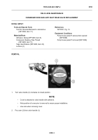
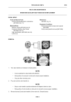
Stop on valve handle is positioned between 90 degrees indent on valve.
•
Note position of valve handle on valve prior to removal to ensure proper installation.
3.
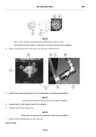
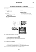
Remove locknut (3) and valve handle (1) from valve (4).
Discard locknut.
4.
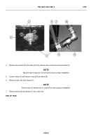
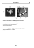
Remove two screws (5) and valve (4) from manual valve control mounting bracket (6).
NOTE
Tag and mark hoses prior to removal to ensure proper installation.
5.
Loosen clamp (7) and remove hose (8) from elbow (9).
6.
Remove hose (10) from elbow (11).
NOTE
Note location of elbows prior to removal to ensure proper installation.
7.
Remove elbow (9) and elbow (11) from valve (4).
END OF TASK
HWT1641
HWT2538
Back to Top

