TM-9-2320-346-10 - Page 1079 of 1184
REMOVE WHEEL AND TIRE ASSEMBLY FROM NO. 1 OR NO. 2 AXLE
1.
Service (inflate) vehicle air suspension to perform jacking procedure.
2.
Turn No. 1 axle ball valves OFF to perform jacking procedure.
CAUTION
Jack placement is critical to avoid damaging vehicle suspension compo-
nents. Follow jack placement notes and procedures carefully. Failure to
comply may result in damage to equipment.
NOTE
•
If wheel and tire assembly to be removed is on No. 3 or No. 4 axle,
refer to remove wheel and tire assembly from No. 3 or No. 4 axle.
•
All wheel and tire assemblies on No. 1 and No. 2 axles are removed
the same. Passenger side No. 1 axle wheel and tire assembly shown.
•
Jack ram should be fully screwed down (making jack as short as
possible) for Step (3).
3.
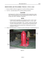
Check if jack base plate (1) and jack (2) will fit under apex of equalizing beam (3):
2
3
1
Figure 2.
TM 9-2320-346-10
0152
0152-3
Back to Top


