TM-9-2320-346-10 - Page 1088 of 1184
NOTE
Check that spare wheel and tire assembly wheel dish is in same position
as flat wheel and tire assembly wheel dish. Deep side of wheel dish will
face toward vehicle on four front wheels. Deep side of wheel dish will face
away from vehicle on four rear wheels except M984A4. All eight wheels
on M984A4 are installed with deep side of wheel dish facing toward ve-
hicle.
2.
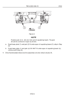
Make sure deep side of spare wheel and tire assembly wheel dish (3) is in same position
as flat/shredded wheel and tire assembly wheel dish when flat/shredded wheel and tire
assembly was removed.
NOTE
•
Tire valve stem extension must be removed to reposition wheel and
tire assembly valve stem extension.
•
It may be necessary to reposition valve stem to accomplish
installation of valve stem extension.
3.
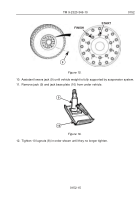
Make sure wheel and tire assembly valve stem (4) is pointing out, away from vehicle.
TM 9-2320-346-10
0152
0152-12
Back to Top


