TM-9-2320-361-20 - Page 235 of 1207
TM 9-2320-361-20
2-20. STE/lCE DESCRIPTION AND OPERATION (Contd)
c. Vehicle Test Meter.
(1) General.
The VTM provides a method for technician to test vehicle electrical and mechanical
components. Readings are either pass/fail indications or digital displays in units familiar to technician
(psi, rpm, volts, ohms, amps, etc.). The VTM interfaces with vehicle directly with a transducer(s) from
Tranducer Kit (TK). Additional tests can also be done that involve manually probing and/or connecting
transducers to appropriate test points. Operating power for VTM is drawn from vehicle batteries or some
equivalent power source. Power is routed to VTM through cable clamps connected to battery. The STE/ICE
general purpose testing capabilities that may be applied to vehicle are: 0-1000 psig pressure, 0-45 volts DC,
and 0-40k ohms resistance. The following control functions can be performed in conjunction with special
tests: interleave (displays rpm with next test), display maximum value, display minimum value, and display
peak-to-peak value.
(2) Controls and Indicators.
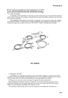
The controls and readout display on VTM are illustrated. The
following paragraphs describe how the controls are used, and how displays function.
(a) Power Switch (PUSH ON/PULL OFF).
The power switch controls DC power to VTM.
The VTM can operate from either a 12-volt or 24-volt battery system. When power switch is pushed in
(PUSH ON), VTM power is on. To shut VTM off, pull out power switch (PULL OFF). The power switch
contains a 4-amp circuit breaker. If a fault occurs and VTM uses more power than it should, power
switch will pop out automatically. Check your hookup carefully and try again before returning VTM to
support maintenance.
(b) TEST SELECT Switches.
The TEST SELECT switches are used to select actual test to be
performed. There are ten positions on each switch, numbered 0 through 9. The number dialed into these
switches is read by VTM when you press TEST button. Changing TEST SELECT switch positions has no
effect until TEST button is pushed on.
(c) TEST Button.
Depressing and releasing TEST button causes test measurement to begin.
Observe measured value on readout display. The reading will be in units normally used for a particular
vehicle measurement. These units are listed on the flip cards. The TEST button must be pressed and
immediately released. Depressing and holding TEST button down initiates an offset test. Offset tests are
described in TM 9-4910-571-12&P.
(d) Readout Display.
The readout display will show different types of readouts during testing
up to a maximum of 4 characters (for example .8.8.8.8). Types of readouts are described in detail in
paragraph (3) and are summarized as follows:
1. Status Readout.
This type of readout keeps technician informed of what is happening
such as power applied, failed test, etc.
2. Numerical Readout.
This type of readout is the measured value in units of the
measurement being made. If you are measuring 0-45 volts DC, the number 24 on display indicates 24 volts.
3. Error Readout.
This type of readout indicates that wrong test number was selected,
transducer is not connected, or VTM is faulty.
(e) Flip Cards.
The flip cards list the 2-digit test number system for selecting various tests.
The cards also summarize test and operating instructions contained herein.
(f) Transducer Cable Connector J4.
Connectors J2 and J3 connect VTM to any transducer
in transducer kit. Operating power is supplied to transducer, and signals from transducers ar supplied to
VTM through the cable. Connectors J2 and J3 are identical and can be interchanged with each other or used
in combination.
(g) Test Probe Cable Connector J4.
Connector J4 connects test leads to VTM when doing
manual voltage and resistance tests.
2-150
Back to Top


