TM-9-2320-361-20 - Page 791 of 1207
TM 9-2320-361-20
12-6.
FRONT SPLASH GUARD REPLACEMENT (M35A2C, M36A2)
This task covers:
a. Removal
b. Installation
INITIAL SETUP:
APPLICABLE MODELS
REFERENCES (TM)
M35A2C, M36A2
TM 9-2320-361-10
MATERIALS/PARTS
TM 9-2320-361-20P
Ten locknuts
EQUIPMENT CONDITION
Parking brake set (TM 9-2320-361-10).
NOTE
Left and right front splash guards are removed the same. This
procedure covers the left front splash guard.
a. Removal
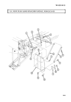
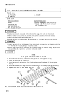
1. Remove two locknuts (13) and screws (8) from splash guard braces (6) and front splash guard (14).
Discard locknuts (13).
2. Remove two locknuts (4), screws (5), and splash guard braces (6) from frame (2). Discard
locknuts (4).
NOTE
Perform step 3 only if pioneer tool kit is on vehicle.
3. Remove two locknuts (15) and screws (7) from front splash guard (14) and pioneer tool kit
bracket (1). Discard locknuts (15).
4. Remove two locknuts (3), screws (16), and splash guard (14) from frame (2). Discard locknuts (3).
NOTE
Perform step 5 for M35A2C vehicles.
5. Remove two locknuts (9), screws (12), plate (10), and bumper (11) from front splash guard (14).
Discard locknuts (9).
b. Installation
1.
2.
3.
4.
5.
12-8
NOTE
Perform step 1 for M35A2C vehicles.
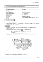
Install bumper (11) and plate (10) on front splash guard (14) with two screws (12) and new
locknuts (9).
Install front splash guard (14) on frame (2) with two screws (16) and new locknuts (3).
NOTE
Perform step 3 only if pioneer tool kit is installed on vehicle.
Install front splash guard (14) on pioneer tool kit bracket (1) with two screws (7) and new
locknuts (15).
Install two splash guard braces (6) on frame (2) with two screws (5) and new locknuts (4).
Install two splash guard braces (6) on front splash guard (14) with screws (8) and new locknut (13).
Back to Top

