TM-9-2320-361-20 - Page 817 of 1207
TM 9-2320-361-20
12-21. DISCHARGE VALVE CONTROL LEVERS MAINTENANCE (M49A2C) (Contd)
c. Cleaning and Inspection
1. Refer to para. 2-10 for general cleaning instructions.
2. Refer to para. 2-10 for general inspection instructions.
Table 12-1. M49A2C Discharge Valve Control Lever Wear Limits.
ITEM
lTEM/POINT OF MEASUREMENT
WEAR LIMITS/TOLERANCES
NO.
INCHES
MILLIMETERS
21
Lever arm (inner diameter at shaft hole)
0.443 - 0.463
11.25 - 11.76
14
Lever arm (inner diameter at shaft hole)
0.430 - 0.454
10.92 - 11.53
4 and 28
Levers (inner diameter at shaft hole)
0.868 - 0.922
22.05 - 23.42
10, 24, and 29
Bushings end exposed (diameter)
0.430 - 0.438
10.92 - 11.13
8
Lever shaft (diameter)
0.860 - 0.885
21.84 - 22.48
11 and 18
Roller (outer diameter)
0.750
19.05
11 and 18
Roller (inner diameter)
0.440 - 0.444
11.18 - 11.28
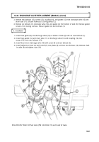
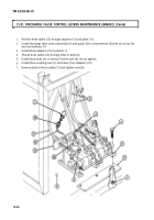
3. Inspect clevis (26) and pin (25) for cracks or pin hole damage. Replace clevis (26) and pin (25) if
cracked or pin hole is damaged.
4. Inspect shaft (9) for twists, cracks, or breakage. Replace shaft, (9) if twisted, cracked, or broken.
5. Inspect lever arms (14) and (21) for wear, cracks, or pin hole damage. Refer to table 12-1, M49A2C
Discharge Valve Control Lever Wear Limits, for measurements. Replace lever arms (14) and (21) if
not within wear limits.
6. Inspect cams (13) and (19) for cracks or broken tabs. Replace cams (13) and (19) if cracked or tabs
are broken.
7. Inspect rollers (11) and (18) for flat spots or wear. Refer to table 12-1, M49A2C Discharge Valve Control
Lever Wear Limits, for measurements. Replace rollers (11) and (18) if not within wear limits.
8. Inspect brackets (5), (30), and (23) for cracks or damage. Replace brackets (5), (30), and (23) if
cracked or damaged.
9. Inspect installed bushings (10), (24), and (29) for grooves or wear. Refer to table 12-1, M49A2C
Discharge Valve Control Lever Wear Limits, for measurements. Replace bushings (10), (24), and (29)
if not within wear limits.
NOTE
Perform steps 10 through 12 if bushings or brackets are damaged or
not within wear limits.
10. Press bushings (10), (24), and (29) from brackets (5), (23), and (30).
11. Install bushings (10) and (24) in brackets (5) and (23) with press until bushings (10) and (24) ends
are flush with inward side surface of brackets (5) and (23).
12. Install bushing (29) in bracket (30) with press until bushing (29) ends extend 0.5 in. (12.7 mm) from
bracket (30) sides.
13. Inspect levers (4) and (28) for wear, latch, handle, or rod change. Refer to table 12-1, M49A2C
Discharge Valve Control Lever Wear Limits, for measurements. Replace levers (4) and (28) if not
within wear limits.
14. Inspect lever shaft (8) for grooves or wear. Refer to table 12-1, M49A2C Discharge Valve Control
Lever Wear Limits, for measurements. Replace lever shaft (8) if not within wear limits.
15. Inspect springs (22) and (31) for distorted or broken coils. Replace springs (22) and (31) if distorted
or coils are broken.
12-34
Back to Top

