TM-9-2320-361-20 - Page 871 of 1207
TM 9-2320-361-20
12-54. SPEED CONTROL CABLE MAINTENANCE
This task covers:
a. Removal
c. Installation
b. Inspection
d. Adjustment
INITIAL SETUP:
APPLICABLE MODELS
M49A2C, M50A2, M50A3
TOOLS AND TEST EQUIPMENT
STE/ICE
MATERIALS/PARTS
Two cotter pins
Two lockwashers
REFERENCES (TM)
TM 9-2320-361-10
TM 9-2320-361-20P
EQUIPMENT CONDITION
Parking brake set (TM 9-2320-361-10).
GENERAL SAFETY INSTRUCTIONS
Keep fire extinguisher nearby when working on fuel
tank trucks.
WARNIN G
Do not perform this procedure while smoking or within 50 feet of
sparks or open flame. Fuel is flammable and can explode easily,
causing injury or death to personnel and damage to equipment.
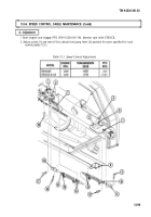
1. Remove cotter pin (16) and pin (17) from eye (18) and fuel pump lever (2). Discard cotter pin (16).
2. Loosen two nuts (14) and remove cable assembly (15) from bracket (3).
3. Remove cotter pin (9) and pin (12) from eye (11) and rod assembly (7). Discard cotter pin (9).
4. Remove two screws (5), lockwashers (6), and bracket (8) from cab frame (4). Discard lockwashers (6).
5. Loosen two nuts (13) and remove cable (15) from bracket (8).
6. Loosen two nuts (10) and remove two eyes (11) and (18) from cable (15).
b. Inspection
Inspect bracket (8) for cracks and bends. Replace bracket (8) if cracked or bent.
c. Installation
1. Install two eyes (11) and (18) on cable assembly (15) and tighten two nuts (10).
NOTE
Access to bracket is through door in cab floor in front of driver’s seat.
2. Install bracket (8) on frame (4) with two screws (5) and new lockwashers (6).
3. Install cable (15) on fuel pump lever (2) with pin (17) and new cotter pin (16).
4. Install cable (15) on rod assembly (7) with pin (12) and new cotter pin (9).
NOTE
Loosen nuts to adjust cable so fuel pump lever is in curb idle position.
5. Install cable (15) on two brackets (3) and (8) and tighten two nuts (14) and (13).
12-88
Back to Top


