TM-9-2320-361-20 - Page 927 of 1207
TM 9-2320-361-20
This task covers:
a. Removal
c. Assembly
b. Disassembly
d. Installation
INITIAL SETUP:
APPLICABLE MODELS
REFERENCES (TM)
M764
TM 9-2320-361-10
MATERIALS/PARTS
TM 9-2320-361-20P
Eight locknuts
GM grease (Appendix C, Item 13)
EQUIPMENT CONDITION
Parking brake set (TM 9-2320-361-10).
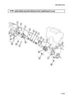
1. Remove four locknuts (14), screws (15), and yoke flange (3) from power divider flange (1). Discard
locknuts (14).
2. Remove four locknuts (10), screws (12), and shaft flange (9) from clutch drive flange (11). Discard
locknuts (10).
1. Inspect two universal joints (13) for looseness or roughness. Replace universal joint(s) (13) if
damaged (para. 7-4).
2. Loosen cap (7) and remove shaft (8), cap (7), washer (6), seal (5), and yoke (4).
3. Remove three lubrication fittings (2).
1. Apply GAA grease to splines of shaft (8).
2. Install seal (5), washer (6), and cap (7).
3. Slide shaft (8) into yoke (4) and tighten cap (7).
4. Install three lubrication fittings (2).
1. Install shaft flange (9) on clutch drive flange (11) with four screws (12) and new locknuts (10). Do not
tighten locknuts (10).
2. Install yoke flange (3) on power divider flange (1) with four screws (15) and new locknuts (14).
Tighten four locknuts (10) and (14) 90-120 lb-ft (122-163 N-m).
12-144
Back to Top


