TM-9-2320-361-20 - Page 941 of 1207
12-95.
TM 9-2320-361-20
“
This task covers:
a. Removal
b. Installation
INITIAL SETUP:
APPLICABLE MODELS
REFERENCES (TM)
M764
LO 9-2320-209-12-1
MATERIALS/PARTS
TM 9-2320-361-10
TM 9-2320-361-20P
Six
locknuts
Sealing compound (Appendix C, Item 25)
EQUIPMENT CONDITION
Cap and plug set (Appendix
C, Item 8)
•Parking brake set (TM 9-2320-361-10).
PERSONNEL
REQUIRED
ŽHydraulic oil level gage and screen removed
(para. 12-88).
Two
CAUTION
When disconnecting hydraulic hoses, plug all openings to prevent
dirt from entering and causing internal parts damage. Remove
plugs prior to installation.
NOTE
ŽTag hoses for proper installation.
ŽHave
drainage
container
ready to catch oil.
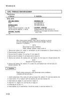
1. Remove two locknuts (13), screws (1), and deflector (2) from crossmember (12). Discard locknuts (13).
2. Remove plug (5) and drain oil.
3. Remove hose (9), adapter (10), and tee (11) from nipple (3).
4. Remove hose (8), adapter (7), and elbow (6) from nipple (4).
5. Remove two locknuts (19), washers (20), and retainer (14) from body (21). Discard locknuts (19).
NOTE
Assistant will help with step 6.
6. Remove two locknuts (18), washers (17), screws (16), and hydraulic tank (15) from body (21).
Discard locknuts (18).
NOTE
ŽApply sealing compound to male pipe
•l Assistant will help with step 1.
threads before installation.
1. Install hydraulic tank (15) on body (21) with two screws (16), washers (17), and new locknuts (18).
2. Install retainer (14) on body(21) with two washers (20) and new locknuts (19).
3. Install elbow (6), adapter (7), and hose (8) on nipple (4).
4. Install tee (11), adapter (10), and hose (9) on nipple (3).
5. Install plug (5) on tee (11).
6. Install deflector (2) on crossmember (12) with two screws (1) and new locknuts (13).
12-158
Back to Top


