TM-9-2320-361-20 - Page 943 of 1207
12-96.
TM 9-2320-361-20
This task covers:
a. Removal
c. Assembly
b. Disassembly
d. Installation
INITIAL SETUP:
APPLICABLE MODELS
REFERENCES (TM)
M764
TM 9-2320-361-10
MATERIALS/PARTS
Three lockwashers
Two woodruff keys
TM 9-2320-361-20P
EQUIPMENT CONDITION
• Parking brake set (TM 9-2320-361-10).
Three cotter pins
ŽEarth boring machine seat frame removed (para. 12-92).
Maintenance procedures are the same for feed and drive levers.
This procedure covers the drive lever.
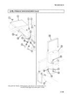
1. Remove nut (11), screw (17), and latch (16) from bracket (12).
2. Remove cotter pin (7), clevis pin (9), and clevis (8) from lever (10). Discard cotter pin (7).
3. Remove nut (21), screw (19), plate (20), and operating handle (22) from lever (10).
4. Remove three screws (14), lockwashers (13), and bracket (12) from main support tube (15). Discard
lockwashers (13).
5. Loosen two screws (24) and remove two arms (25), rod (3), and two woodruff keys (23) from
cams (18). Discard woodruff keys (23).
1. Remove two cotter pins (28) from shaft (27). Discard cotter pins (28).
2. Remove shaft (27), two bushings (26), and levers (10) from bracket (12).
NOTE
To maintain proper operation lever travel distance, note length of
threads visible at each end of pushrod.
3. Remove two nuts (1), rod (3), two springs (2), and stop (4) from pushrod (5).
4. Remove clevis (8) and nut (6) from pushrod (5).
NOTE
For steps 1 and 2, ensure visible threads match measurements
noted in disassembly.
1. Install nut (6) and clevis (8) on pushrod (5).
12-160
Back to Top


