TM-9-2320-361-20 - Page 951 of 1207
12-102.
TM 9-2320-361-20
This task covers:
a. Front Splash Guard Removal
c.
Rear Splash Guard Installation
b. Rear Splash Guard Removal
d. Front Splash Guard Installation
INITIAL SETUP:
APPLICABLE MODELS
REFERENCES (TM)
M756A2
TM 9-2320-361-10
MATERIALS/PARTS
TM 9-2320-361-20P
Eleven locknuts
EQUIPMENT CONDITION
Parking brake set (TM 9-2320-361-10).
NOTE
• Left and right front splash guards are removed the same, except
for fuel tank brace on left side. This procedure is for the right
front splash guard.
• Perform steps 1 and 2 if brace is damaged and requires replace-
ment.
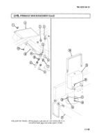
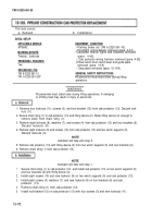
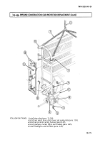
1. Remove fuel tank (para. 3-24).
2. Remove locknut (2), screw (5), and brace (4) from fuel tank support (3). Discard locknut (2).
3. Remove locknut (6), screw (8), and brace (4) from splash guard (7). Discard locknut (6).
4. Remove
two locknuts (10), screws (9), and splash guard (7) from toolbox (1). Discard locknuts (10).
NOTE
Left and right rear splash guards are removed the same. This
procedure
is for the right rear splash guard.
1. Remove two locknuts (18) and (16), screws (19) and (14), and brace (17) from frame (15) and splash
guard (20). Discard locknuts (18) and (16).
2. Remove two locknuts (13), screws (12), and splash guard (20) from mounting bracket (22). Discard
locknuts (13). Discard locknuts (13).
3. Remove three locknuts (21), screws (23), and mounting bracket (22) from frame (11). Discard
locknuts (21).
NOTE
Left and right splash guards are installed the same. This procedure
is for the right rear splash guard.
1. Install mounting bracket (22) on frame (11) with three screws (23) and new locknuts (21).
2. Install splash guard (20) on mounting bracket (22) with two screws (12) and new locknuts (13).
3. Install brace (17) on splash guard (20) and frame (15) with two screws (14) and (19) and new
locknuts (16) and (18).
12-168
Back to Top

