TM-9-2320-361-34 - Page 483 of 764
TM 9-2320-361-34
I
15-42. INTERMEDIATE CASE MAINTENANCE
(Contd)
8.
9.
10.
11.
12.
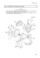
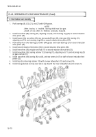
Install boring case (5) on intermediate case (2) (para. 15-38).
Look through inspection hole (4) of boring case (5) and ensure that heel of second reduction drive
pinion (9) is alined with toe of rack drive gear (6), and toe of second reduction feed pinion (8) is alined
with heel of rack feed idler gear (7). If adjustment of
feed pinion (8) is required, refer to subtask
of
this paragraph. If adjustment of drive pinion (9) is required, refer to subtask g.
Look through power leveler shaft hole (1) on intermediate case (2) and ensure that toe of first
reduction drive pinion (12) is alined with toe of drive gear (10) and heel of first reduction feed pinion (3)
is alined with heel of gear and hub (11).
NOTE
Depth of first reduction feed and drive pinions are adjusted by
adding or removing the appropriate shims (para. 15-38).
Position dial indicator through power leveler
shaft hole (1) and against drive gear (10) and measure
backlash between drive gear (10) and first reduction drive pinion (12). Backlash should be
0.006-0.016 in. (0.15-0.41 mm). If adjustment of drive
gear (10) is
required, refer
to subtask h.
Place dial indicator against gear and hub (11) and measure backlash between gear and hub (11) and
first reduction drive pinion (12). Backlash should be 0.006-0.016 in. (O. 15-0.41 -mm). If
adjustment
of
gear and
hub (11) is required, refer to subtask i.
15-172
Back to Top


