TM-9-2320-366-20-1 - Page 45 of 1824
TM 9-2320-366-20-1
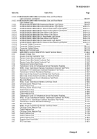
Figure No.
Figure Title
Page
1-11.
M1096 Truck, Chassis: 5-Ton, 6x6, LWB .
.......................................
1-13
1-12.
Powertrain .
.............................................................
1-15
1-13.
Engine Air Intake System .
..................................................
1-17
1-14.
Fuel System .
............................................................
1-18
1-15.
Cooling System .
.........................................................
1-20
1-16.
Electrical System .
........................................................
1-23
1-17.
Engine Starting System. .
...................................................
1-24
1-18.
Service Lighting System .
...................................................
1-25
1-19.
Blackout Lighting System .
..................................................
1-26
1-20.
Instrument Panel .
........................................................
1-27
1-21.
Material Handling Crane (MHC) System .
........................................
1-28
1-22.
Troubleshooting Aid .
......................................................
1-29
1-23.
M1089 Underlift System .
...................................................
1-30
1-24.
Brake System .
...........................................................
1-31
1-25.
Steering System .
.........................................................
1-33
1-26.
15K Self-Recovery Winch (SRW) .
.............................................
1-34
1-27.
M1084/M1086 Material Handling Crane (MHC) .
...................................
1-35
1-28.
MHC Control Station and Remote Control .
......................................
1-36
1-29.
M1089 Material Handling Crane (MHC), 30K Winches, and Underlift .
...................
1-37
1-30.
M1089 30K Winches .
......................................................
1-40
1-31.
M1089 Underlift .
.........................................................
1-41
1-32.
Air Transportability Hydraulic System .
..........................................
1-42
1-33.
Air System .
.............................................................
1-44
2-1.
Circuit Breaker Locations .
.................................................
2-159
7-1.
Power Distribution Panel (PDP) Circuit Beakers, Diodes, and Relays .
...................
7-38
11-1.
Front Brake Shoe Service Criteria .
............................................
11-4
11-2.
Rear Brake Shoe Service Criteria .
...........................................
11-11
11-3.
Rear Brake Air Hose Locations .
............................................
11-119
11-4.
Cargo/Dump Rear Brake Control Air Hose Locations .
............................
11-122
11-5.
Tractor Rear Brake Control Air Hose Locations.
.................................
11-125
11-6.
Front Brake Air Hose Locations.
............................................
11-130
17-1.
M1084/M1086 Material Handling Crane (MHC) Hydraulic Hose Locations.
...............
17-20
17-2.
M1084/M1086 Material Handling Crane (MHC) Hydraulic Tubing Locations .
.............
17-32
17-3.
M1089 Material Handling Crane (MHC) Hydraulic Hose Locations .
....................
17-54
17-4.
M1089 Material Handling Crane (MHC) Hydraulic Tubing Locations .
...................
17-63
17-5.
15K Self-Recovery Winch (SRW) Hydraulic Hose Locations (All Models Except
M1090/M1094) .
........................................................
17-123
17-6.
M1090/M1094 15K Self-Recovery Winch (SRW) Hydraulic Hose Locations .
............
17-125
17-7.
M1089 15K Self-Recovery Winch (SRW) Hydraulic Hose Locations .
..................
17-129
17-8.
M1089 30K Winch Left/Right Hydraulic Hose and Tubing Locations .
..................
17-131
19-1.
Hydraulic Manifold PN HFC32598 Rear View .
...................................
19-11
19-1.1. Hydraulic Manifold PN 65234 Rear View .
.......................................
19-12
19-1.2. M1089 Wrecker Control Panel External Power Hydraulic Hose and Tubing Locations .
.......
19-25
19-2.
M1089 Wrecker Control Panel Pressure and Function Hydraulic Hose and Tubing
Locations .
.............................................................
19-26
19-3.
Air Transportability Hydraulic Hose Locations .
...................................
19-62
19-4.
M1090/M1094 Hydraulic Hose Locations .
......................................
19-71
19-5.
M1089 Underlift Hydraulic Hose Locations .
.....................................
19-74
19-6.
M1089 Underlift Hydraulic Tubing Locations .
....................................
19-79
19-7.
M1089 Hydraulic System Hose Locations.
......................................
19-89
23-1.
Primary Air Supply Hose Locations .
...........................................
23-3
23-2.
Central Tire Inflation System (CTIS) Air Hose Locations .
............................
23-5
23-3.
Air Transportability Air Hose Locations.
........................................
23-10
23-4.
M1090/M1094 Air Hose Locations .
...........................................
23-13
Change 1
v
Back to Top


