TM-9-2320-366-20-1 - Page 49 of 1824
TM 9-2320-366-20-1
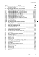
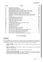
Table No.
Table Title
Page
11-6.
Front Brake Air Hose Locations .
.........................................
11-130
14-1.
M1088 Platform Attaching Hardware .
......................................
14-61
16-1.
M1089 Rear Clearance Marker Light Connectors .
............................
16-167
17-1.
M1084/M1086 Material Handling Crane (MHC) Hydraulic Hose Locations.
............
17-20
17-2.
M1084/M1086 Material Handling Crane (MHC) Hydraulic Tubing Locations .
..........
17-32
17-3.
M1089 Material Handling Crane (MHC) Hydraulic Hose Locations .
.................
17-54
17-4.
M1089 Material Handling Crane (MHC) Hydraulic Tubing Locations .
................
17-63
19-1.
M1089 Wrecker Control Panel External Power Hydraulic Hose and Tubing Locations .
...
19-25
19-2.
M1089 Wrecker Control Panel Pressure and Function Hydraulic Hose and Tubing
Locations .
..........................................................
19-26
19-3.
Air Transportability Hydraulic Hose Locations .
................................
19-62
19-4.
M1090/M1094 Hydraulic Hose Locations .
...................................
19-71
19-5.
M1089 Underlift Hydraulic Hose Locations .
..................................
19-74
19-6.
M1089 Underlift Hydraulic Tubing Locations .
.................................
19-79
19-7.
M1089 Hydraulic System Hose Locations .
...................................
19-89
23-1.
Air Supply Hose Locations.
...............................................
23-3
23-2.
Central Tire Inflation System (CTIS) Air Supply Hose Locations .
....................
23-5
23-3.
Air Transportability Air Hose Locations .
.....................................
23-10
23-4.
M1090/M1094 Air Hose Locations .
........................................
23-13
23-5.
30K Winch Air Hose Locations.
...........................................
23-15
E-1.
Pneumatic Tube Lengths .
................................................
E-17
E-2.
Non-Metallic Electrical Cable Conduit Lengths .
................................
E-21
E-3.
M1089 30K Air Hose Lengths and Fittings .
...................................
E-29
F-1.
Dry Torque Limits for SAE and ANSI Screws and Free Spinning Nuts .
................
F-2
F-2.
Dry Torque Limits for SAE and ANSI Prevailing Torque Nuts .
.......................
F-4
F-3.
Dry Torque Limits for Metric Screws and Free Spinning Nuts .
.......................
F-5
F-4.
Dry Torque Limits for Metric Prevailing Torque Nuts .
.............................
F-6
F-5.
Wet Torque Limits for SAE and ANSI Screws and Free Spinning Nuts .
................
F-7
HOW TO USE THIS MANUAL
OVERVIEW
This Technical Manual (TM) is provided to help you maintain the MTV at the Unit Maintenance level. Because of its
size, it is divided into five volumes. Volumes 3, 4, and 5 contain information which will assist you in the performance
of Unit Maintenance on the MTV. Volume 1 contains the following major sections in order of appearance:
•
WARNING SUMMARY.
Provides a summary of the most important warnings that apply throughout the
manual.
•
TABLE OF CONTENTS.
Lists, for all volumes, the chapters, sections, appendixes, and indexes with page
numbers in order of appearance.
•
CHAPTER 1, INTRODUCTION.
Describes the MTV and provides equipment data.
•
CHAPTER 2, VEHICLE MAINTENANCE.
This chapter contains information for finding tools; special tools;
Test, Measurement, and Diagnostic Equipment (TMDE); and repair parts. It also contains the preventive
maintenance checks and services (PMCS) and troubleshooting tables.
Change 1
ix
Back to Top


