TM-9-2320-366-20-4 - Page 1021 of 1558
TM
TM 9-2320-366-20-4
9-2320-366-20-4
14-11. M1088 FIFTH WHEEL ADJUSTMENT
This task covers:
a. Top Plate Locking Mechanism Adjustment
b. Sliding Mechanism Adjustment
c. Follow-On Maintenance
INITIAL SETUP
Equipment Conditions
Semitrailer uncoupled (TM 9-2320-366-10-1).
Engine shut down (TM 9-2320-366-10-1).
Tools and Special Tools
Tool Kit, Genl Mech (Item 46, Appendix C)
Gage, Profile (Item 21, Appendix B)
a. Top Plate Locking Mechanism Adjustment.
NOTE
• Rubber bushing on yoke shaft between top plate
casting and adjustment nut should rotate with
resistance.
• If unable to rotate rubber bushing, turn adjusting
nut to the left.
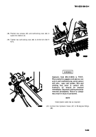
(1) Insert profile gage in split locks (1).
(2) Lock fifth wheel (TM 9-2320-366-10-1).
(3) Rotate rubber bushing (2) between top plate casting (3)
and adjustment nut (4).
NOTE
• Turning adjustment nut to the right will increase
split lock pressure on the profile gage. Turning
adjustment nut to the left has the opposite
effect.
• When properly adjusted, profile gage can be
rotated in split locks with some resistance.
(4) Turn adjusting nut (4) until profile gage fits snug in split
locks (1) but will rotate with resistance.
(5) Unlock fifth wheel (TM 9-2320-366-10-1).
(6) Remove profile gage from split locks (1).
14-91
14-91
Back to Top

