TM-9-2320-366-20-4 - Page 519 of 1558
TM 9-2320-366-20-4
8-16. M1088/M1089 TRANSMISSION AUXILIARY OIL COOLER HOSE REPLACEMENT
This task covers:
a. Removal (S/N 0001-7167)
b. Installation (S/N 0001-7161)
c. Removal (S/N 7162 and higher)
d. Installation (S/N 7162 and higher)
e. Follow-On Maintenance
INITIAL SETUP
Equipment Conditions
Batteries disconnected (para 7-57).
Tools and Special Tools
Goggles, Industrial (Item 15, Appendix C)
Pan, Drain (Item 24, Appendix C)
Tool Kit, Genl Mech (Item 46, Appendix C)
Wrench, Torque, 0-200 lb-in. (Item 59, Appendix C)
Socket Set, Socket Wrench (Item 34, Appendix C)
Wrench, Torque, 0-175 lb-ft (Item 58, Appendix C)
Crowfoot Attachment, Socket Wrench (Item 12.1,
Appendix B)
Materials/Parts
Dispenser, Pressure Sensitive Adhesive Tape
(Item 20, Appendix D)
Cap and Plug Set (Item 14, Appendix D)
Ties, Cable, Plastic (Item 69, Appendix D)
Nut, Self-Locking (2) (Item 167, Appendix G)
Nut, Self-Locking (2) (Item 154, Appendix G)
Nut, Self-Locking (2) (Item 152, Appendix G)
Washer, Spring (2) (Item 291, Appendix G)
Packing, Preformed (2) (Item 178.1, Appendix
G)
Personnel Required
(2)
WARNING
•
Wear
appropriate
eye
protection
when
working under vehicle due to the possibility
of falling debris.
Failure to comply may
result in injury to personnel.
•
Ensure
exhaust
system
is
cool
before
performing maintenance. Failure to comply
may result in injury to personnel.
NOTE
Vehicle serial numbers 0001-7161 may have
transmission
oil
cooler
tubes
installed.
Vehicle serial numbers 7162 and higher will
have transmission oil cooler hoses installed.
a. Removal (S/N 0001-7161).
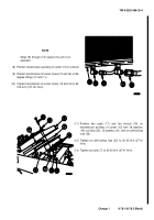
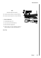
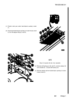
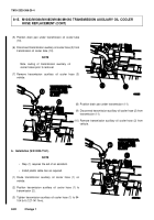
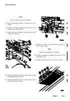
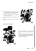
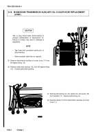
(1) Remove two self-locking nuts (1), washers (2), and
screws (3) from heat shield (4).
Discard self-locking
nuts.
(2) Remove two self-locking nuts (5), spring washers (6),
washers (7), screws (8), washers (9), and heat shield (4)
from transmission auxiliary oil cooler (10). Discard self-
locking nuts and spring washers.
Change 1
8-85
Back to Top

