TM-9-2320-366-34-2 - Page 733 of 1434
TM 9-2320-366-34-2
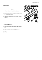
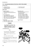
c. M1090/M1094 Removal.
NOTE
• Left and right side of valve control panel is
removed the same way. Right side shown.
• Remove plastic cable ties as required.
• Steps (1) through (9) require the aid of an
assistant.
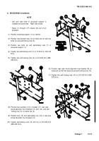
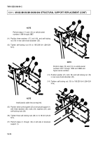
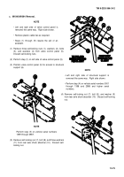
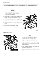
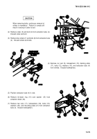
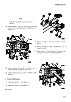
(1) Remove three self-locking nuts (1), washers (2), bolts
(3), and washers (4) from valve control panel (5).
Discard self-locking nuts.
(2) Perform step (1) on left side of valve control panel (5).
(3) Position valve control panel (5) for access to structural
support (6).
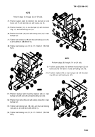
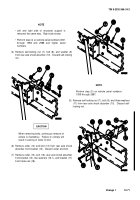
NOTE
• Left and right side of structural support is
removed the same way. Right side shown.
• Perform step (4) on vehicle serial numbers 0001
through 1398 and 2988 and higher serial
numbers.
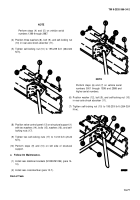
(4) Remove self-locking nut (7), bolt (8), and washer (9)
from rear axle shock absorber (10). Discard self-locking
nut.
NOTE
Perform step (5) on vehicle serial numbers
1399 through 2987.
(5) Remove self-locking nut (7), bolt (8), and three washers
(11) from rear axle shock absorber (10). Discard self-
locking nut.
13-75
Back to Top

