TM-9-2320-386-24-1-1 - Page 1014 of 1078
TM 9-2320-386-24-1-1
0283 00
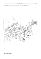
CTIS ELECTRONIC CONTROL UNIT (ECU)/BRACKET REPLACEMENT (Contd)
0283 00-2
REMOVAL
1.
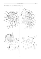
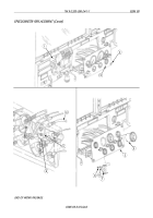
Remove four screws (10) and faceplate (9) from ECU (6).
2.
Remove four screws (8), lockwashers (7), and ECU (6) from ECU mounting bracket (14). Discard
lockwashers (7).
3.
Remove screw (18), ground (GND) strap (4), and jumper ground (GND) lead (5) from ECU (6).
4.
Disconnect cannon plugs (2) and (3) from ECU (6).
5.
Remove two screws (15), lockwashers (16), washers (17), jumper ground (GND) lead (5), and
lockwasher (19) from ECU mounting bracket (14) and instrument panel (1). Discard
lockwashers (16) and (19).
6.
Remove two screws (13), lockwashers (12), washers (11), and ECU mounting bracket (14) from
instrument panel (1). Discard lockwashers (12).
INSTALLATION
NOTE
Jumper ground (GND) lead is installed on lower left corner of
ECU mounting bracket.
1.
Install ECU mounting bracket (14) and jumper ground (GND) lead (5) on instrument panel (1) with
new lockwasher (19), two washers (17), new lockwashers (16), and screws (15).
2.
Install ECU mounting bracket (14) on instrument panel (1) with two washers (11), new
lockwashers (12), and screws (13).
3.
Connect cannon plugs (2) and (3) to ECU (6).
4.
Install jumper ground (GND) lead (5) and ground (GND) strap (4) on ECU (6) with screw (18).
5.
Install ECU (6) on mounting bracket (14) with four new lockwashers (7) and screws (8).
6.
Install faceplate (9) on ECU (6) with four screws (10).
7.
Connect battery ground cable (WP 0121 00).
Back to Top


