TM-9-2320-387-24-2 - Page 640 of 1555
TM 9-2320-387-24-2
I
1528.
ENGINE INSTALLATION (Cont’d)
43.
44.
45.
46.
47.
48.
49.
50.
51.
52.
53.
54.
55.
56.
57.
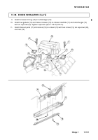
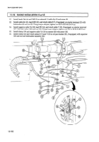
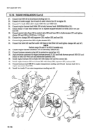
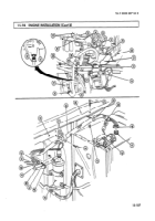
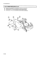
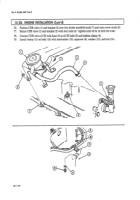
Install cable assembly (1) on throttle shaft lever (4) with accelerator cable clip (7).
Install cable assembly (1) on cable bracket (2) and tighten two nuts (8).
Connect throttle return spring (3) to cable bracket (2).
NOTE
Steps
46
through 51 cover accelerator linkage adjustment.
Loosen nuts (8) on cable assembly (1) and cable bracket (2).
Fully depress accelerator pedal.
Hold throttle shaft lever (4) on injection pump (5) in full-throttle position.
Adjust two nuts (8) up or down so cable end (6) holds throttle shaft lever (4) in full-throttle position.
Tighten two nuts (8) connecting cable assembly (1) to cable bracket (2).
Release accelerator pedal and ensure throttle shaft lever (4) returns all the way to idle position.
WARNING
Ensure fuel pump vent line is properly attached to top vent line
fitting of fuel pump. Improper vent line installation may cause
injury to personnel or damage to equipment.
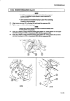
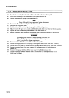
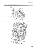
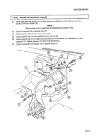
Connect vent line (22) to fuel pump (17) and tighten clamp (20).
Connect fuel supply line (21) to fuel pump (17) and tighten clamp (18) to lo-20 lb-in. (l-2 Nom).
Connect fuel return hose (19) to fuel return line (24) and tighten clamp (23) to lo-20 lb-in. (l-2 Nom).
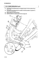
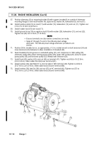
Connect two water hoses (9) to water crossover (12) and water pump (14) and tighten two
clamps (10).
Connect water pump inlet hose (16) to water pump (14) and tighten clamp (15).
Connect surge tank-to-water crossover hose (11) to crossover (12) and tighten clamp (13) to
lo-20 lb-in. (l-2 N=m).
15-108
Back to Top

