TM-9-2330-342-10 - Page 62 of 500
PALLETIZED LOAD SYSTEM TRAILER (PLST) M1076 A1 - Continued
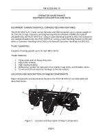
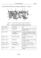
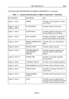
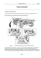
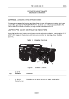
loaded flatracks. ISO containers are loaded/unloaded onto the PLST M1076 A1 (Figure 1,
Item 7) using the Load Handling System (LHS) with either a Container Handling Unit (CHU)
or Enhanced Container Handling Unit (ECHU). This is done with the use of the cart (Figure
1, Item 1) that is located on the back of the PLST M1076 A1 (Figure 1, Item 7). The cart
(Figure 1, Item 1) can be positioned in three different configurations (container mode,
flatrack mode, or stored on the bumper) depending on the mission. Guides (Figure 1, Item
2) laterally position the FR on the trailer rear stops (Figure 1, Item 8) and these locate the
longitudinal position of the FR in relation to the PLST M1076 A1 (Figure 1, Item 7). These
stops prevent the FR from sliding rearward. A pneumatic locking device (Figure 1, Item 6),
located between the frame rails just above the second axle, hooks to engage the lock points
and secure the FR to the PLST M1076 A1 (Figure 1, Item 7). An air valve controls the
position of the lock hooks. Springs retain the hooks in the locked position. The PLST M1076
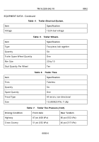
A1 (Figure 1, Item 7) has a standard 12 volt electrical system with 24 volt military adapters.
Also provided are two intervehicular electrical connecting cables (Figure 1, Item 3) of
sufficient length to reach the towing vehicle. Two towing eyes, at the rear of the PLST M1076
A1 (Figure 1, Item 7) permit towing with a medium-duty tow bar. The spare-tire carrier is
behind the first axle (Figure 1, Item 5). The spare-tire is held in place with bolts through the
wheel bolt pattern. The spare tire and wheel assembly can be raised and secured in the
spare tire carrier by the trailer-provided hand-operated winch. The PLST M1076 A1 (Figure
1, Item 7) uses turntable-type steering for tracking and turning and is equipped with a two
position adjustable drawbar (Figure 1, Item 4). The PLST M1076 A1 (Figure 1, Item 7) is
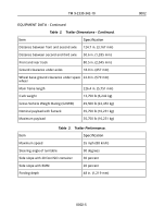
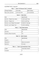
also equipped with an air braking system. All three axles use 16.5 in. diameter by 7 in. wide
(419 mm by 178 mm) S-cam brakes. The PLST M1076 A1 (Figure 1, Item 7) has a dual
brake system with separate service and emergency brake system. The PLST M1076 A1
(Figure 1, Item 7) brake system is activated and charged by the vehicle air supply. The
brakes are self-adjusting.
PLST SERVICE BRAKES
The six service brakes on the PLST M1076 A1 are powered by 24/20 in. (610/508 mm)
brake chambers. Six-inch automatic slack adjusters are provided with all brake chambers.
The service brakes are activated when a signal from the foot-operated treadle valve or hand-
operated control valve is sent through a series of relay valves. The relay valves convert the
proportioned service-brake signal from the vehicle into a regulated service brake chamber
pressure.
PLST PARKING BRAKES
Spring-chamber parking brakes are provided on all PLST M1076 A1 axles. The application
and release of the six PLST M1076 A1 spring brakes is controlled by a spring brake control
valve. An absence of air pressure in the emergency/spring-brake supply line causes the
spring-brake control valve to activate the spring brake. The spring brake control valve also
retains air pressure in the PLST M1076 A1 air reservoir so the PLST M1076 A1 spring
brakes can be released by the spring release valve. The spring-brake control valve also
TM 9-2330-342-10
0003
0003-2
Back to Top


