TM-9-2330-342-10 - Page 63 of 500
PLST PARKING BRAKES - Continued
prevents compounding of pressures in the brake chamber by relieving the pressure on the
spring brake side of the chambers when the spring brakes are set and the service brakes
are applied. The PLST M1076 A1 spring brake release valve is located on the right front
corner of the trailer. This valve releases the PLST M1076 A1 spring brakes without a prime
mover air supply when there is sufficient air reservoir pressure. After the spring brakes have
been released, they can be reapplied by actuating the release valve. When air is supplied
through the emergency/spring-brake supply line, the spring release valve is overridden and
the trailer spring-brakes are released. If there is insufficient air reservoir pressure to release
the trailer parking brakes, a cage nut release is provided on each spring chamber to
mechanically release the spring brakes.
PLST EMERGENCY BRAKES
Whenever there is a loss of pressure from the vehicle or PLST M1076 A1 air reservoir, the
emergency brakes are activated.
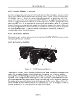
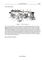
PLST MECHANICAL SYSTEM
4
5
6
1
2
3
7
Figure 2.
PLST Mechanical System.
The drawbar (Figure 2, Item 3) provides a means to tow, steer, and adjust the length of the
trailer. The turntable (Figure 2, Item 2) allows the front axle to turn on axis to provide
steering. The main frame (Figure 2, Item 1) provides a mounting place for the rest of the
systems. Three spring-mounted axles (Figure 2, Item 5) provide a cushioned ride for loads.
Spring-operated parking brakes (Figure 2, Item 6) provide safe parking without air pressure.
During operation, service brakes provide braking power. Safety chains (Figure 2, Item 4)
on the drawbar attach to the tow vehicle as a safety backup. Load locks (Figure 2, Item 7)
provide the means to lock the flatrack to the trailer for transport.
TM 9-2330-342-10
0003
0003-3
Back to Top

