TM-9-2330-342-10 - Page 64 of 500
PLST ELECTRICAL SYSTEM
5
8
1
2
3
4
5
6
7
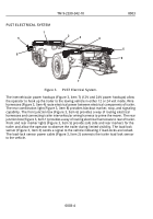
Figure 3.
PLST Electrical System.
The intervehicular power hookups (Figure 3, Item 7) (12V and 24V power hookups) allow
the operator to hook up the trailer to the towing vehicle in either 12 or 24 volt mode. Wire
harnesses (Figure 3, Item 4) route electrical power between electrical components of trailer.
The rear combination light (Figure 3, Item 8) provides blackout marker, stop, and signaling
capability. The front junction box (Figure 3, Item 6) provides a way of routing electrical
harnesses and connecting trailer intervehicular wiring harness to prime the mover. The rear
junction box (Figure 3, Item 1) provides a way of routing electrical harnesses to rear of trailer.
Front and rear marker lights (Figure 3, Item 5) provide safe side and rear markers for the
trailer and allow the operator to observe the trailer during limited visibility. The load-lock
sensor (Figure 3, Item 3) sends a signal to the vehicle indicating if load-locks are locked.
The load-lock sensor power cable (Figure 3, Item 2) connects the trailer load lock sensor
to the vehicle.
TM 9-2330-342-10
0003
0003-4
Back to Top

