TM-9-2330-342-23-P - Page 196 of 1348
STEP 12
Is continuity measured across wire 1008B between diode assembly connector, terminal 7 and the rear
junction box?
WARNING
Remove all jewelry such as rings, ID tags, bracelets, etc. prior to working on or around vehicle.
Jewelry and tools can catch on equipment, contact positive electrical circuits, and cause a
direct short, severe burns, or electrical shock. Failure to comply may result in injury or death
to personnel.
1.
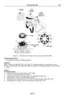
Remove cover from rear junction box (WP
0058).
DIODE
ASSEMBLY
COVER
REAR JUNCTION
BOX
C
L
O
S
E
O
P
E
N
DIODE
ASSEMBLY
CONNECTOR
6
5
4
3
2
1
7
8
9
10
11
12
TERMINAL
7
WIRE 1008B
1435
1435
1008B
1012B
1680C
1678C
1003C
1004C
Figure 12.
Diode Assembly Connector, Rear Junction Box, and Wire 1008B.
2.
Connect button probe cable red lead to wire 1008B at diode assembly connector, terminal 7.
3.
Connect button probe cable black lead to wire 1008B at rear junction box.
4.
Perform ICE Test 91.
5.
Meter should display a reading of less than 200 ohms.
TM 9-2330-342-23&P
0014
0014-12
Back to Top


