TM-9-2350-238-20-1 - Page 1023 of 1364
TM 9-2350-238-20-1
2
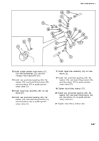
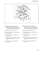
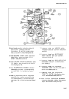
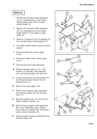
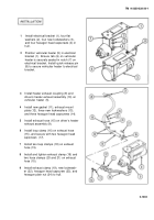
Install spade control instruction plate (4),
7
If removed, install new MASTER switch
two machine screws (5), two new
instruction plate (19) to driver’s instrument
Iockwashers (6), and two hexagon plain
nuts (7) to driver’s instrument panel (8).
3
Install ENGINE START switch instruction
plate (9) and two drive screws (10) on
driver’s instrument panel (8).
4
Install UTILITY OUTLET identification plate
(11) and two drive screws (12) on driver’s
instrument panel (8).
panel (8).
8
If removed, install new
switch instruction plate
instrument panel (8).
9
If removed, install new
identification plate (21)
ment panel (8).
10
If removed, install new
INSTRUMENT
(20) to driver’s
BO-IR SELECTOR
to driver’s instru-
INFRARED
5
Install SUSPENSION LOCKED indicator
RECEIVER switch instruction plate (22) to
lamp instruction plate (13) and two drive
driver’s instrument panel (8).
screws (14) to driver’s instrument panel
(8).
11
If removed, install new HYDRAULIC
PUMP/PTO CLUTCH identification plate
6
Install SUSPENSION VALVE instruction
(23) to driver’s instrument panel (8).
plate (15), two machine screws (16), two
new Iockwashers (17), and two hexagon
12
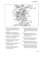
Install CLUTCH OPERATION WARNING
plain nuts (18) on driver’s instrument panel
instruction plate (24) and four drive screws
(8).
(25) to driver’s instrument panel (8).
2-997
Back to Top

