TM-9-2350-238-20-1 - Page 1099 of 1364
TM 9-2350-238-20-1
3
4
5
6
7
8
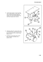
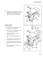
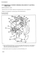
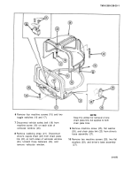
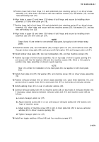
Connect circuit breaker to wiper motor and
defroster switch electrical lead assembly
(3) to toggle switch (8).
Connect wiper motor to switch electrical
lead (9) to toggle switch (8).
Connect defroster ground lead disconnects
electrical lead (10) to wiper motor and
defroster lead disconnects electrical lead
assembly (4).
Position defroster ground lead disconnects
electrical lead (10) and wiper motor to
switch electrical lead (9) on windshield
wiper motor assembly (11), and secure
with new lockwasher (12) and machine
screw (13).
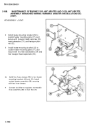
Install machine screw (14), loop clamp
(15), and new self-locking nut (16).
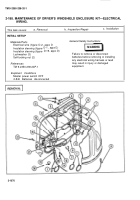
Connect circuit breaker to wiper motor and
defroster switch electrical lead assembly
9
10
11
12
(3) to toggle switch (17) and circuit breaker
behind driver's seat.
Connect disconnect defroster to switch and
ground lead disconnect electrical lead (18)
to toggle switch (17).
Connect defroster to switch and ground
lead disconnect electrical lead (19) to
wiper motor and defroster lead disconnects
electrical lead assembly (4).
Position disconnect defroster to switch and
ground lead disconnect electrical lead (18)
and defroster to switch and ground lead
disconnect electrical lead (19) on defroster
(20), and secure with two machine screws
(21), two new
lockwashers (22), and two
hexagon plain nuts (23).
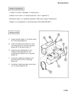
Install tiedown strap (24) and three marker
bands (25).
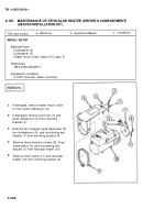
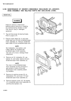
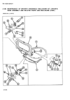
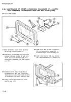
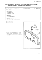
2-189. MAINTENANCE OF DRIVER’S WINDSHIELD ENCLOSURE KIT—DRIVER’S
BASE ASSEMBLY AND RELATED PARTS AND ENCLOSURE.
This task covers: a.
Remova/
b.
lnspection/Repair
c. Installatbn
INITIAL SETUP
MaterialslParts
General Safety Instructions
Cotter pin (2)
LockWasher
LockWasher (2)
LockWasher (4)
Failure to remove or disconnect
LockWasher (6)
batteries before removing or installing
Self-locking nut (4)
any electrical wiring harness or lead
may result in injury or damaged
References
equipment.
TM 9-2350-238-24P-1
Equipment Conditions
MASTER power switch OFF
2-640 Batteries disconnected
2-1073
Back to Top

