TM-9-2350-238-20-1 - Page 206 of 1364
TM 9-2350-238-20-1
2-12. ELECTRICAL CIRCUIT TROUBLESHOOTING (CONT).
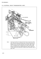
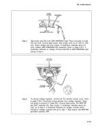
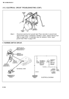
Step 6.
Place red probe in plug pin G (lead 2). Ground black probe. Start engine
and run at 1000 to 1200 rpm. Check voltage and stop engine. If
multimeter indicates about 24 volts, replace voltage regulator. Refer to
page 2-557. If multimeter indicates no voltage, connect wiring harness to
voltage regulator and troubleshoot generator. Refer to page 2-43.
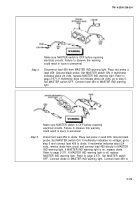
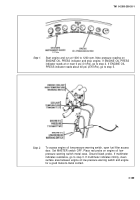
Step 7.
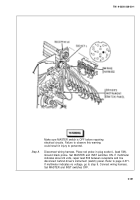
To access bulkhead disconnect, remove driver’s seat, refer to page 2-952;
and remove driver's compartment aft cowl, refer to page 2-928. Discon-
nect wiring harness at bulkhead disconnect. Place jumper wire to pin D
and socket D (lead 459). Place jumper wire to pin C and socket C (lead
27). Place red probe on pin E (lead 506). Ground black probe. Set
MASTER and INST switches ON. If multimeter indicates about 24 volts,
go to step 8. If multimeter indicates no voltage, remove jumper wire (lead
459) and connect wiring harness to bulkhead disconnect and go to step 9.
Set MASTER and INST switches OFF.
2-180
Back to Top

