TM-9-2350-238-20-1 - Page 602 of 1364
TM 9-2350-238-20-1
2-73. MAINTENANCE OF DRIVER’S INSTRUMENT PANEL (GAGE) (CONT).
REASSEMBLY
NOTE
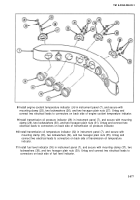
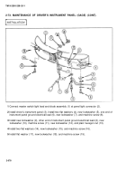
Steps 1 thru 3 are written for one panel light, but apply to both.
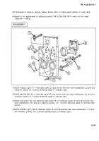
1
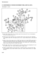
If removed, install new electrical wires (1).
2
Install flat washer (2), LED (3), and cap (4) in socket housing (5).
3
Install panel light (6) in instrument panel (7), and secure with two new lockwashers (8) and two
machine screws (9).
4
Install generator charge warning light (1 0) in instrument panel (7), and secure with two new
lockwashers (11) and two machine screws (12). Untag and connect electrical leads to
connectors of generator charge warning light.
5
Install engine and transmission warning light (13) in instrument panel (7), and secure with two
new Iockwashers (14) and two machine screws (15). Untag and connect electrical leads to
connectors of engine and transmission warning light.
6
Install battery/generator voltmeter (1 6) in instrument panel (7), and secure with mounting clamp
(17), two lockwashers (18), and two hexagon plain nuts (19). Untag and connect electrical lead
to connector on back side of battery/generator voltmeter.
7
Install engine oil pressure gage (20)
(21 ), two lockwashers (22), and two
leads to connectors on back side of
in instrument panel (7), and secure with mounting clamp
hexagon plain nuts (23). Untag and connect two electrical
engine oil pressure gage.
2-576
Back to Top

