TM-9-2350-238-34-2 - Page 108 of 327
TM 9-2350-238-34-2
6 No leakage is allowed around open port (5), around hydraulic piston (1), or around boom
cylinder head (6).
7
If leakage occurs, disassemble boom control cylinder assembly (2) and check for damaged
parts.
8 If no leakage occurs, reduce pressure and remove hydraulic line or hose (4).
9 Drain hydraulic fluid (item 10, appx B) and plug cylinder ports (3) and (5).
INSTALLATION
●
Hydraulic system is under high
pressure. Follow hydraulic
system safety procedures to
prevent injury (TM 9-2350-
238-20-2). Wipe up all spilled
hydraulic fluid.
●
Make sure hydraulic system is
depressurized before performing
any hydraulic maintenance to
prevent injury to personnel.
●
Use hoist with minimum lifting
capacity of 2000 lb (908 kg) to
prevent injury to personnel and
damage to equipment.
NOTE
●
Another M578 Recovery Vehi-
cle or M88A1 Recovery Vehicle
may be used, if available, for
lifting.
●
The following steps are written
and illustrated for installation of
one boom winch control
cylinder assembly, but apply to
both .
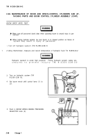
1 Secure sling around boom winch control
cylinder assembly (1). Lift boom winch
control cylinder assembly and lower
through cab door into place.
2-95
Back to Top


