TM-9-2350-256-10 - Page 366 of 796
MEASURING A SLOPE
1.
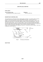
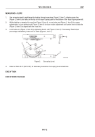
Use surveying level to sight target by looking through eye piece (Figure 2, Item 7), aligning cross line
(Figure 2, Item 6) (left side) on the top of the slope if going uphill or the bottom of the slope if going downhill.
2.
While sighting on target with cross line (Figure 2, Item 6), move index arm (Figure 2, Item 3) for coarse
adjustments, or turn setting knob (Figure 2, Item 4) for slow motion adjustment until center level vial bubble
(Figure 2, Item 5) is aligned with the cross line.
3.
Lock index arm (Figure 2, Item 3) by tightening thumb nut (Figure 2, Item 2) if necessary. Read slope
percentage indicated by index arm on scale (Figure 2, Item 1).
Figure 2.
Surveying Level.
4.
Refer to FM 4-30.31 (WP 0131) for alternate procedures if surveying level is defective.
END OF TASK
END OF WORK PACKAGE
TM 9-2350-256-10
0067
0067-2
Back to Top

