TM-9-2350-256-10 - Page 397 of 796
PAYOUT MAIN WINCH CABLE BY BACKTRACKING FROM DISABLED VEHICLE - Continued
CAUTION
Start payout of main winch cable slowly. Fast initial payout can cause the cable to unspool.
Failure to comply may result in damage to the main winch.
12.
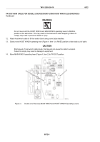
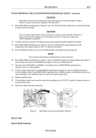
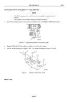
Move MAIN WINCH operating lever (Figure 9, Item 3) to PAYOUT position after slack is removed and begin
to payout main winch cable.
CAUTION
Do not increase engine speed unless necessary to continue reverse direction movement. If
engine rpm must be increased, do not over speed main winch. Failure to comply may
result in damage to equipment.
13.
Continue reverse movement until slightly past previously prepared spade emplacement location.
14.
Move MAIN WINCH operating lever (Figure 9, Item 3) to HOLD position, apply brakes, and shift
transmission shift selector (Figure 9, Item 1) to Neutral (N) position.
15.
Move SPADE lever (Figure 9, Item 2) to LOWER position until spade touches the ground.
NOTE
This procedure will maintain constant tension on the main winch.
16.
Move MAIN WINCH operating lever (Figure 9, Item 3) to INHAUL position and release brakes with spade on
ground while continuing to hold SPADE lever (Figure 9, Item 2) in LOWER position.
17.
Use main winch (WP 0080) to pull M88A1 onto spade and move MAIN WINCH operating lever
(Figure 9, Item 3) to HOLD position.
18.
Increase engine speed and move MAIN WINCH operating lever (Figure 9, Item 3) to INHAUL position to
recover disabled vehicle. Keep MAIN WINCH operating lever in INHAUL position until disabled vehicle is as
close as possible. This will keep tension on main winch cable during inhaul.
19.
Release operating lever.
20.
Chock disabled vehicle and move the main winch operating lever to PAYOUT position to release tension on
the main winch cable.
21.
Disconnect cables and stow equipment.
Figure 9.
Main Winch Lever and Transmission Selector.
END OF TASK
END OF WORK PACKAGE
TM 9-2350-256-10
0072
0072-13/blank
Back to Top

