TM-9-2350-256-10 - Page 649 of 796
OPERATOR MAINTENANCE
TRACK TENSION ADJUSTMENT (OLD CONFIGURATION)
INITIAL SETUP:
Tools and Special Tools
General mechanic's tool kit
(WP 0135, Table 1, Item 2)
Tanker bar (crowbar pinch, 5 ft)
(WP 0132, Table 2, Item 12)
Track adjusting wrench
(WP 0132, Table 2, Item 90)
Materials/Parts
Hardwood lumber (WP 0134, Table 1, Item 53)
Personnel Required
Crewman (3)
References
Chocking vehicle (WP 0103)
TRACK TENSION ADJUSTMENT (OLD CONFIGURATION)
WARNING
When backing the vehicle, two personnel must guide operator. Both guides must stand to
the same side of vehicle at a safe distance. Front guide must be visible to operator. Failure
to comply may result in personnel death, injury, and/or damage to equipment.
1.
Move vehicle back and forth two or three times over hard level ground. Coast to a stop without braking.
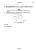
Center track shoe (Figure 1, Item 1) over No. 2 support roller (Figure 1, Item 4).
2.
Chock vehicle (WP 0103).
3.
Pry up track and place a 6 in. (152 mm) by 1 in. (25 mm) thick block (Figure 1, Item 5) between No. 2
support roller (Figure 1, Item 4) and track.
4.
Place straight edge or taut line (Figure 1, Item 3) flush with tops of No. 2 support roller (Figure 1, Item 4) and
No. 3 support roller (Figure 1, Item 2).
5.
Measure distance (D) between centers of No. 2 and No. 3 support rollers (Figure 1, Items 2 and 4).
Figure 1.
Setup for Adjusting Tension.
TM 9-2350-256-10
0109
0109-1
Back to Top

