TM-9-2350-256-20-1 - Page 258 of 948
TM 9-2350-256-20-1
0053 00
CORRECTIVE ACTION –Continued
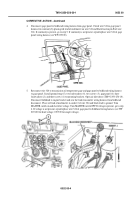
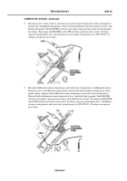
4.
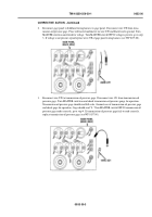
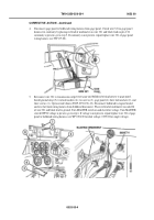
Disconnect gage panel to bulkhead wiring harness from gage panel. Check wire 321 in gage panel
harness for continuity by placing red lead of multimeter on wire 321 and black lead on pin C. If
continuity is present, go to step 5. If continuity is not present, repair/replace wire 321 of gage panel
wiring harness (see WP 193 00).
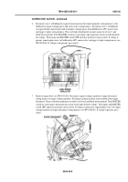
5.
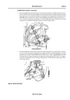
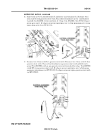
Reconnect wire 321 to transmission oil pressure gage and bulkhead wiring harness to gage panel.
Install ground strap (5), two lockwashers (4), two screws (3), gage panel (6), three lockwashers (2), and
three screws (1). Open air inlet doors (TM 9-2350-256-10). Disconnect bulkhead to engine bracket
and rear fuel tank wiring harness from bulkhead disconnect. Place red lead of multimeter in socket K
of wire 321 and black lead to ground. Turn MASTER switch on and check for voltage. Turn MASTER
switch OFF. If voltage is present, go to step 6. If voltage is not present, repair/replace wire 321 of gage
panel to bulkhead wiring harness (see WP 0194 00 for dual voltage; 0195 00 for single voltage).
0053 00-4
Back to Top


