TM-9-2350-256-20-1 - Page 29 of 948
TM 9-2350-256-20-1
HOW TO USE THIS MANUAL
MANUAL CONTENT
Overview
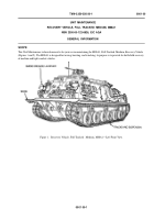
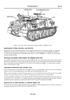
This manual contains unit maintenance instructions for the M88A1 Medium Full-Tracked Recovery Vehicle.
The front matter in this manual consists of general warnings, title block page, and table of contents.
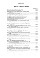
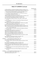
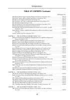
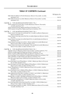
The information contained in this manual is presented in chapters and Work Packages. Each chapter is divided into Work
Packages (WPs) that cover general information, troubleshooting procedures, maintenance procedures, and other information for
specific systems or components. Each WP starts on a right-hand page with a page number of 1. Page numbers consist of the WP
number followed by a dash and another number. For example, "0014 00-7" means WP 0014 00, page 7.
At the end of this manual are an alphabetical index, schematics, DA Form 2028-2, and a metric conversion chart.
Chapters
Chapter 1 provides general information, equipment description, and theory of operation.
Chapter 2 provides the troubleshooting procedures.
Chapter 3 provides general unit maintenance instructions including service upon receipt, the PMCS, and lubrication.
Chapter 4 provides unit maintenance instructions for the powerplant.
Chapter 5 provides unit maintenance instructions for the fuel, air intake, and exhaust systems.
Chapter 6 provides unit maintenance instructions for the engine cooling system.
Chapter 7 provides unit maintenance instructions for the electrical systems and circuits.
Chapter 8 provides unit maintenance instructions for the transmission and output reduction drives.
Chapter 9 provides unit maintenance instructions for the suspension system.
Chapter 10 provides unit maintenance instructions for the hull- and cab-related components.
Chapter 11 provides unit maintenance instructions for the personnel heater and connection components, and fixed fire extin-
guisher system.
Chapter 12 provides unit maintenance instructions for main winch, hoist winch, and related components.
Chapter 13 provides unit maintenance instructions for the main hydraulic system.
Chapter 14 provides unit maintenance instructions for the Auxiliary Power Unit (APU).
Chapter 15 provides unit maintenance instructions for the M8A3 gas/particulate filter unit.
Chapter 16 provides unit maintenance instructions for the M239 smoke grenade launcher system.
Chapter 17 provides unit maintenance instructions for the exhaust smoke generating system.
Chapter 18 provides unit maintenance instructions for the USAREUR safety lighting modification kit.
Chapter 19 provides unit maintenance instructions for the deep water fording kit.
Chapter 20 provides supplementary maintenance instructions including decal markings replacement, preparation for storage and
shipment, an illustrated list of manufactured items, and torque limits.
Chapter 21 provides supporting information including the titles of documents and publications referenced in this manual, the
MAC and special tools list, an expendable and durable items list, a tool ID list, and a list of mandatory replacement parts.
Alphabetical Index
An index is located after the last WP in this manual that provides an alphabetical listing of information and components/assem-
blies contained in this manual.
Schematics
There are three schematics in the form of foldouts located at the end of this manual. One schematic for the hydraulic system and
four for the electrical system (two schematics for the dual voltage system and two schematics for the single voltage system).
xvii
Back to Top

