TM-9-2350-261-20-4 - Page 271 of 767
TM 9-2350-261-20-4
REPLACE M8A3/M14 NBC CABLES AND SWITCH ASSEMBLY (M113A2
ONLY) — Continued
0690 00
4.
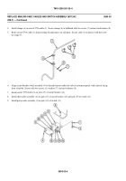
Install clamps (6) on circuit 579A cable (1). Secure clamps (6) to bulkhead with two screws (7) and new lockwashers (8).
5.
Route circuit 579A cable (1) along existing wiring harness on side plate. Secure cable (1) to harness with three new
tie straps (9).
6.
Align circuit breaker switch assembly (9) to threaded inserts under left side of instrument panel, with controls facing
front o f
carrier
. Secure with two screws (6), w ash e rs (7 ), an d new lo cknu ts (8) .
7.
Install circuit 579A lead (16) on jack (17) of circuit breaker (14).
8.
Install short cable assembly (12) on jack (13) of circuit breaker (14) and jack (15) of switch (11).
9.
Install power cable assembly (4) on jack (10) of switch (11).
0690 00-4
Back to Top

