TM-9-2350-261-20-4 - Page 369 of 767
TM 9-2350-261-20-4
REPLACE SMOKE GENERATOR GLOW PLUG CABLE ASSEMBLIES
(M1059 ONLY) — Continued
0714 00
INSTALLATION
NOTE
There are two exterior cables, access plates, and smoke generators, left and right. Cables are
installed on
carrier
the same way. O nly one ext erior cable, access plate, and smoke generator i s
shown. Remove cables as required.
1.
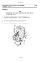
Install interior cable (1), four screws (2), and new locknuts (3) to right access plate (4).
2.
Connect exterior cable (5) to preheat harness jack (6) on panel (7) of right smoke generator (8).
3.
Connect exterior cable (5) to interior cable (1) in right access plate (4).
4.
Install interior cable (1), four screws (2), and new locknuts (3) to left access plate (4).
5.
Connect exterior cable (5) to interior cable (1) in left access plate (4).
6.
Connect exterior cable (5) to preheat harness jack (6) on panel (7) of left smoke generator (8).
0714 00-4
Back to Top


