TM-9-2350-261-20-4 - Page 370 of 767
TM 9-2350-261-20-4
REPLACE SMOKE GENERATOR GLOW PLUG CABLE ASSEMBLIES
(M1059 ONLY) — Continued
0714 00
NOTE
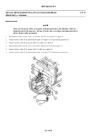
T here are seven clamps t hat b olt interior cable t o h ull. O n e i s u sed on the rig
ht side of
carrier
and six on the left. All are installed the same way. Only one clamp is shown. Install as required.
7.
Install interior cable (1), six clamps (9), screws (10), and new lockwashers (11) to hull.
8.
Install interior cable (1), clamp (9), screw (10), and new lockwasher (11) to hull.
9.
Connect interior cable (1) to jack 1J6 (12) on back of control panel (13).
FOLLOW-THROUGH STEPS
1.
Install smoke generator assembly on bracket (WP 0697 00).
2.
Install in-board armor shield (WP 0713 00).
3.
Connect battery ground lead (WP 0294 00).
4.
Set circuit breaker CB1 to ON. See TM 3-1040-283-10.
END OF TASK
0714 00-5/6 blank
Back to Top


