TM-9-2350-261-20-4 - Page 399 of 767
TM 9-2350-261-20-4
REPLACE EXTERNAL COMMUNICATION BOX A11 (M1068 ONLY) — Continued
0723 00
5.
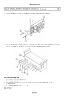
Connect cable W101 (2) from J1 and cable W102 (3) from J4 to curbside data panel assembly (1).
6.
Connect cable W111 (5) from J125, cable W112 (6) from J123, cable W113 (7) from J126, cable W114 (8) from J124,
cable W115 (9) from J136, and cable W118 (10) from J135 and to signal patch panel box A10 (4).
FOLLOW THROUGH STEPS
1.
Connect battery ground lead (WP 0294 00).
2.
Turn MASTER SWITCH to ON (see your -10). Check that electrical system works properly. See TM
11-7010-256-12&P.
3.
Turn MASTER SWITCH to OFF (see your -10).
END OF TASK
0723 00-6
Back to Top


