TM-9-2350-273-BD - Page 185 of 288
TM 9-2350-273-BD
COMMUNICATIONS SYSTEM
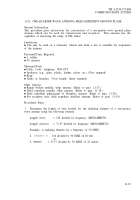
Materials/Tools:
●
Wire, 4-conductor, 18-gauge 5-foot length or cable, telephone, WD-l/TT, 5-foot
llength, (two required) (cut back three steel strands of the two sections)
●
●
●
●
●
●
●
●
Connector, UG-273
Handset, H-189/GR, or standard CVC helmet
Plate, Soviet chest
Transceiver, Soviet, R-123M (with power supply)
Wire, 2-conductor, 12-gauge (minimum size), 3-foot length
Rope, lo-foot length
Gun, soldering
Solder, rosin-core
Other Options:
●
Substitute radio with:
1. Foreign allied equipment (Refer to para. 11-27).
2.
Foreign AN/VRC-12 series equipment. (Refer to para. 11-25.)
Procedural Steps:
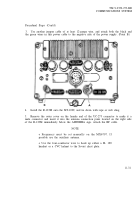
NOTE
The AN/VIC-1 intercom should not have the R-123M wired
through it. For proper operation of the intercom while the
R-123M is being used, set the INSTALLATION SWITCH on
the AM-1780 to INT ONLY position.
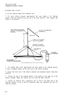
1. Locate the power cable that runs from the turret wall to connection J-21 on the
bottom of MT-1029. Remove the cable from the J-21 connection.
Without removing
the connector from the cable, strip back and remove approximately four inches of the
outer insulation. Stagger the splices, and scrape approximately 1/4 to l/2-inch of the
inner insulation off each of the four wires in the cable.
2.
Use a jumper cable of at least 12-gauge wire, and attach both the red and the
white wires in this power cable to the positive side of the Soviet power supply. (Point
A.)
11-30
Back to Top


