TM-9-2350-273-BD - Page 197 of 288
TM 9-2350-273-BD
COMMUNICATIONS SYSTEM
procedural Steps (Cont'd)
4.
Operating procedures for the R-124.
NOTE
Operating Procedures are keyed to the intercom.
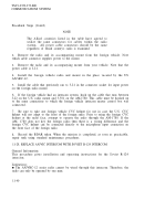
1
. A-1 MAIN JUNCTION BOX
2. FUNCTION SWITCH
3. FUSE
4. VOLUME CONTROL
5. CVC RECEPTACLE
6. VOLTAGE CONNECTION POINT
7. R-112 CONNECTION CABLE
8.
R-123 CONNECTION CABLE I NOT SHOWN)
9. A-4 TERMINATING BOX
10. CVC RECEPTACLE
11. A-3 INTERCONNECTING BOX
12. CVC RECEPTACLE
13. A-2 CONTROL BOX
14. CVC RECEPTACLE
15. FUNCTION SWITCH
a.
Connect the CVC helmet to the chest plate switch. Connect the chest plate
switch to any of the R-124 receptacles (5, 10, 12, or 14 in the intercom figure).
b.
Set FUNCTION SWITCH (2) and FUNCTION SWITCH (15) to the intercom BC
position. (Both function switches must be in the BC position to allow all four boxes
access to intercom.)
c.
Adjust VOLUME CONTROL (4) for desired audio level in the headsets.
5.
Record the BDAR action taken. When the mission is completed, as soon as
practicable, repair tank using standard maintenance procedures.
11-42
Back to Top


