TM-9-2350-277-20-2 - Page 172 of 783
TM 9-2350-277-20-2
PREVENTIVE MAINTENANCE CHECKS AND SERVICES (PMCS), INCLUDING
LUBRICATION INSTRUCTIONS — Continued
0155 00
0155 00-152
Change 5
ITEM
NO.
INTERVAL
MAN-
HOUR
ITEM TO BE
CHECKED OR
SERVICED
CREWMEMBER
PROCEDURE
EQUIPMENT
NOT READY/
AVAILABLE
IF:
e.
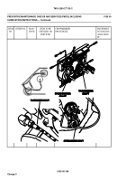
On a sharp angle through this opening, you
will see the back side of the flywheel, as
well as the clearance holes on the flywheel
but through the opening you can only see
one hole at a time.
f.
Looking at the clearance holes, you can also
see the studs and locking nuts that hold the
spline drive ring in place. The spline drive
ring studs and nuts are designed to protrude
into the flywheel’s clearance holes and
clear the flywheel’s holes by approximately
1/4’’.
g.
As in the audio method, use the 3/8’’ bolts
and the breaker bar to detect any backlash.
Turn the engine manually to position one of
the flywheel’s clearance holes in the center
of the flywheel’s cover opening for visual
accessibility.
h.
As the person in the crew compartment
moves the engine, the person under the
vehicle looking into the access hole will
be able to detect one of the following two
relative movements on the spline drive
coupling.
1)
When the spline drive coupling is in
good condition, you can only detect
unit movements because the clearance
between the mating spline teeth is just
a few thousandths of an inch.
Back to Top


