TM-9-2350-277-20-2 - Page 550 of 783
TM 9-2350-277-20-2
REPLACE LEFT/RIGHT TURBO EXHAUST PIPE HEAT SHIELD — Continued
0226 00
INSTALLATION
1.
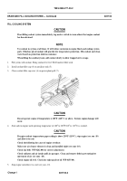
Wrap new insulation cover (1) around exhaust tube (2).
2.
Cut new wire (3) to appropriate length and make two loops at the middle of length around capstan (4) on one half of
insulation cover (1).
3.
Pull wire ends (3) toward corresponding capstan (4) on other half of cover (1). Twist one wire around other to form a
figure eight.
4.
Cross ends of wire (3) behind second capstan (4).
5.
Wind wire ends (3) to approximately 3/4 inch (19 mm) and cut off.
6.
Bend wound ends back around capstan (4) hole.
7.
Repeat Steps 4 - 7 to tie remaining sets of capstans (4) together. Check to make sure that seams are firmly pulled together.
FOLLOW-THROUGH STEPS
1.
Install driver’s power plant access panel, if necessary (WP 0441 00).
2.
Install air cleaner, if necessary (WP 0168 00).
3.
Close power plant access door. See TM 9-2350-277-10.
END OF TASK
0226 00-3/4 blank
Change 5
Back to Top


