TM-9-2350-277-20-3 - Page 795 of 941
TM 9-2350-277-20-3
ADJUST SERVICE BRAKE CONTROL LINKAGE — Continued
0407 00
4.
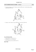
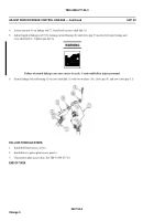
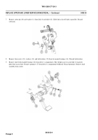
Loosen jam nut (6) on linkage rod (7). Install rod on cross-shaft link (1).
0407 00-4
Change 5
5.
Adjust length of linkage rod (7) by turning rod end bearing (8) until clevis pin (9) inserts freely into bearing and
cross-shaft link (1). Tighten jam nut (6).
WARNING
Failure of control linkage can cause carrier to crash. Crash could kill or injure personnel.
6.
Secure linkage rod end bearing (8) to cross-shaft link (1) with two washers (10), clevis pin (9), and new cotter pin (11).
FOLLOW-THROUGH STEPS
1.
Install hull front access cover ().
2.
Install driver’s power plant access panel ().
3.
Close power plant access door. See TM 9-2350-277-10.
END OF TASK
Back to Top

