TM-9-2350-277-20-5 - Page 206 of 1047
TM 9--2350--277--20--5
0678 00--1
THIS WORK PACKAGE COVERS:
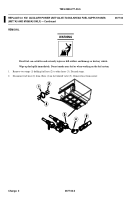
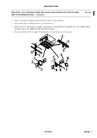
Removal (page 0678 00-1).
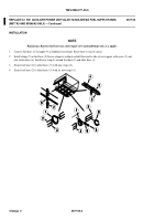
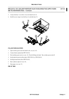
Installation (page 0678 00-4).
INITIAL SETUP:
Maintenance Level
Unit
Tools and Special Tools
General Mechanic’s Tool Kit (WP 0926 00, Item 65)
Materials/Parts
Gasket
Lockwasher (2)
Locknut (1)
Strap (6)
Sleeve (3)
Personnel Required
Unit Mechanic
References
See your -10
Equipment Conditions
Engine stopped (See your -10)
Carrier blocked (See your -10)
Ramp lowered (See your -10)
Battery ground lead disconnected (WP 0338 00)
Personnel heater duct removed (WP 0706 00)
Ri ght front fl oor pl a t e re m ove d (W P 0539 00 or W P 0544
00)
Power plant rear access panel removed (WP 0439 00)
Auxiliary power unit fuel shutoff valve closed (see your
-10)
WARNING
Diesel fuel can catch fire and seriously injure or kill soldiers and damage or destroy vehicle. Wipe
up fuel spills immediately. Do not smoke near fuel or when working on the fuel system.
Change 2
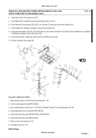
REPLACE 5.0 KW AUXILIARY POWER UNIT BULKHEAD-TO HULL FUEL
SUPPLY HOSES (M577A3 AND M1068A3 ONLY)
0678 00
REMOVAL
Back to Top

