TM-9-2350-277-34 - Page 605 of 871
TM 9-2350-277-34
INSTALL COMMANDER’S CUPOLA ARMOR SHIELDS (M113A3 AND M1064A3 ONLY) —
Continued
0088 00
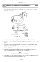
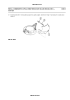
18. Place two 1/16 to 1/8 inch (2 to 3 mm) thick spacers (4) between blocks and shield plate so pintle flange is 1/16 to 1/8
inch (2 to 3 mm) below shield plate.
19. Using a level, check to see that pintle flange (3) and shield plate (1) are level. Make sure machine gun is still centered in
slot. Remove machine gun.
20. Use a welding machine and tack weld pintle flange to shield plate (1) in four places. Then weld pintle to upper surface
on plate with not less than 3/16 inch (4 mm) fillet weld all around pintle flange. Weld in accordance with Class I,
MIL-STD-1261.
21. Raise and lower machine gun mount. Check for interference between ammunition tray and shield plate. Use a hand
grinder and grind off plate, as needed. Apply primer coating. See TM 43-0139.
22. Touch up any damaged areas with enamel paint. See TB 43-0209.
0088 00-4
Back to Top

