TM-9-2350-311-10 - Page 466 of 775
TM 9-2350-311-10
3-6 ARMAMENT AND CAB MAINTENANCE — CONTINUED
3-6.8
Breech Mechanism — Continued
a. Disassembly — Continued
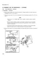
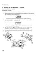
10 Rotate plunger assembly (19) to lock with cam plate (21). Plunger assembly is now held in place and
disengaged from nut (17). Go to step 13.
11
Remove two cap screws (14 or 22), two Iockwashers (15 or 23) and plunger assembly (16 or 19). Go to
step 13.
NOTE
• Perform step 12 for M109A5 M284 cannon assembly containing plunger assembly
11580469.
• When the plunger assembly is pulled out and locked in position B, the nut and spindle
assembly can be removed without the housing and firing group block. Position C allows the
removal of all components.
• If the plunger assembly cannot be pulled out easily, a screwdriver or pry tool can be inserted
between the plunger tip and nut. Applying leverage will free plunger assembly.
12 Move pin (24) located on top of plunger assembly (25), against spring (26) from position A to position B
or C.
3-62
Back to Top

