TM-9-2350-311-10 - Page 70 of 775
TM 9-2350-311-10
1–14 EQUIPMENT OPERATION AND DESCRIPTION — CONTINUED
1-14.7 Suspension System
a.
b.
c.
d.
e.
f.
g.
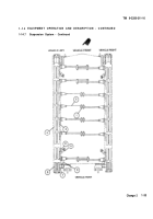
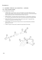
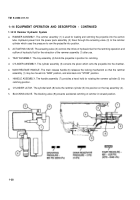
TORSION BAR ANCHORS. The torsion bar anchors (1) secure the ends of the torsion bars (2). One anchor
secures two torsion bars, one from the right and one from the left.
TORSION BARS. The torsion bars (2) are secured at the anchor (1) and connected to the road wheel arm (3). The
torsion bar acts Iike a spring for the road wheel.
ROAD WHEEL ARM. The road wheel arm (3) is connected to the torsion bar (2) and provides a pivot point between
the torsion bar and the road wheel (4).
ROAD WHEELS. The road wheels (4) are suspended from the hull of the howitzer by road wheel arms (3). The
road wheels have two wheel halves separated by a valley to allow track centerguides to pass between the halves.
SHOCK ABSORBERS. The shock absorbers (5) handle differences in the terrain over which the vehicle operates.
They are located on the front and back road wheels (4).
BUMP STOPS. The bump stops (6) keep shock absorbers (5) from moving beyond their limits.
IDLER ARM ASSEMBLY AND TRACK ADJUSTER. The idler arm assembly (7) consists of an idler arm with an
idler wheel (8) attached, all rotating within the idler arm housing. The angle of the idler arm and wheel is determined
by the length of the track adjuster (9). The track tension maybe increased or decreased by adding or removing
grease (item 17, Appx D) to or from the track adjuster.
1-32
Back to Top

