TM-9-2350-311-20-1 - Page 1077 of 1275
TM 9-2350-311-20-1
12-6 AIR OUTLET ORIFICE CONNECTORS
This task covers:
a. Removal
b. Installation
ApplicabIe Configurations
.
Retaining ring pliers (item 40, Appx H)
M109A4/M109A5
Tools
Lockwashers (3) (item 192, Appx G)
General mechanic’s tool kit (item 64, Appx H)
Retaining ring (item 14, Appx G)
a. Removal
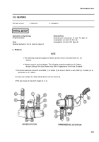
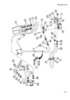
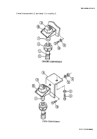
1 Remove clamp (1) and hose assembly (2) from coupling (3).
2 Remove coupling (3).
NOTE
Step 3 applies to connector in crew compartment.
3 Remove two screws (4), two iockwashers (5), and orifice connector and bracket (6). Discard iockwashers.
4 Remove retaining ring (7) and connector (8). Discard retaining ring.
NOTE
Nut is in crew compartment only.
5 Remove screw (10), Iockwasher (11 ), nut (9), and bracket (12). Discard Iockwasher.
b. Installation
NOTE
Nut is in crew compartment only.
1 Install bracket (12), new Iockwasher (11 ), screw (10), and nut (9).
2 Install connector (8) and new retaining ring (7).
NOTE
Step 3 applies to connector in crew compartment.
3 Install orifice connector and bracket (6), two new Iockwashers (5), and two screws (4).
4 Install coupling (3).
12-16
Materials/Parts
Back to Top

