TM-9-2350-311-20-1 - Page 1070 of 1275
TM 9-2350-311-20-1
12-3 HEATERS
This task covers:
a. Removal
b. Installation
Applicable Configuration
S
.
.
Materials/Parts
M109A4/M109A5
External-tooth Iockwashers (4) (item 75, Appx G)
Lockwashers (4) (item 76, A
PPX
G)
Tools
Lockwashers (2) (item 192, Appx G)
General mechanic’s tool kit (item 64, Appx H)
a. Removal
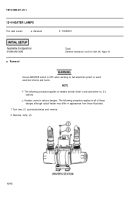
NOTE
The following procedure applies to heaters at both driver's and cannoneer no. 2’s
stations.
Heaters come in various designs. The following procedure applies to all of these
designs although the actual heater may differ in appearance from those illustrated.
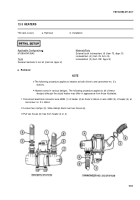
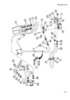
1 Disconnect electrical connector wire 439B (1) of heater (2) at driver’s station or wire 439C (3) of heater (4) at
cannoneer no. 2’s station.
2 Loosen two clamps (5). Slide clamps back over two hoses (6).
3 Pull two hoses (6) free from heater (2 or 4).
12-9
Back to Top

