TM-9-2350-311-20-1 - Page 1063 of 1275
TM9-2350-311-20-1
12-1 AIR PURIFIER
This task covers:
a. Testing
b. Removal
c. Disassembly
d. Assembly
e. Installation
Applicable Configurations
Materials/Parts
M109A4/M109A5
Lockwashers (4) (item 85, A
PPX
G)
Lockwasher (item 95, Appx G)
General mechanic’s tool kit (item 64, A
PPX
H)
Airflow tester (item 62, A
PPX
H)
TM 3-6660-316-10
TM 10-277
FM 3-5
NOTE
For additional information, refer to TM 3-6660-316-10. For information on NBC
decontamination refer to FM 3-5.
a. Testing
1
2
3
4
5
6
7
8
9
10
11
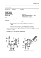
Remove spring clip (1) from air purifier (2).
Disconnect hose (3) from air purifier manifoid (4). Cover opening with solid airflow cap (5).
Cover two purifier openings with airflow caps (5) having small holes.
Disconnect hose (6) at driver’s heater.
Remove calibrated orifice from tester case.
Position magnehelic gage where it can be easily read, and zero gage using adjustment screw.
Attach hose (6) to calibrated orifice.
Turn on MASTER power switch.
Turn on NBC power switch.
Read gage. If airflow is from 2.0 to 4.7 in. H
2
0 (0.50 to 1.17 kPa), it is acceptable. Proceed to step
is not acceptable, proceed to step 11.
Adjust airflow by inserting screwdriver through left center slot (7) and into adjuster. Turn adjuster
counterclockwise to increase and clockwise to decrease airflow.
12. If airflow
12-2
Tool s
References
Back to Top


