TM-9-2350-311-20-1 - Page 1072 of 1275
TM 9-2350-311-20-1
b. Installation
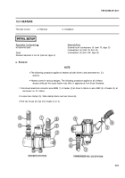
1
2
3
4
5
NOTE
The following procedure applies to heaters at both driver’s and cannoneer no. 2’s
stations.
Some new heaters may require installation of a mounting plate kit to allow control
knob to be seen. Instructions to install kit are included with heater.
External-tooth Iockwashers are to be installed between mounting blocks or bracket
and heaters.
Step 1 applies to heater (4) at cannoneer no. 2’s station.
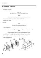
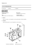
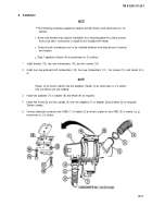
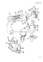
Install bracket (15), two new Iockwashers (14), and two screws (13).
Install four new external-tooth Iockwashers (12), four new Iockwashers (11 ), four screws (10), and heater (2 or
4).
NOTE
Heater (2) at driver’s station has two adapters. Heater (4) at cannoneer no. 2’s station
has one elbow and one adapter.
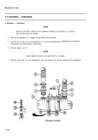
Install two adapters (7) or adapter (8) and elbow (9) as required.
Install two hoses (6) and two clamps (5) over two adapters (7) or adapter (8) and elbow (9) as required.
Tighten clamps.
. .
. ,
.
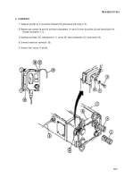
Connect electrical connector wire 439B (1 ) to heater (2) at driver's station or wire 439C (3) to heater
cannoneer no. 2’s station.
(4) at
12-11
Back to Top


